Enhancing efficiency: strain gauge based smart sensors with IO-Link interface
Introduction
Strain gauge based sensors have reached a high level of maturity with strain gauge technology establishing itself as the standard in industrial environments, and the clear choice when it comes to measuring mechanical quantities such as strain, force, weight, or torque. Alongside tasks in research and development and quality assurance, it is widely used in process applications. In clas-sic mechani- cal and plant engineering, there are countless processes and applications where these quantities must be meas- ured as primary, or secondary parameters, for process control and prod-uct quality. Examples include:
- Force measurement technology: pressing, resistance welding, rolling, joining, crimping, end-of-line quality checks, bending processes, bearing force control.
- Weighing technology: checkweighers, filling systems, silo weighing, truck and train scales, load control in production processes
- Torque measurement technology: end-of-line test cells for parts and components such as gearboxes, door handles, screwing processes
Strain gauge-based sensors often make up the core element of a system or application, playing a key role in two aspects.
- Providing measurement values for control systems to control actuators. Accurate measurement results are crucial as any inaccuracies could lead to significant issues, including product rejection.
- As valuable sources of information for quality assur- ance, their reliability is paramount.
Moreover, requirements in terms of tighter tolerances and improved product quality are increas-ing, and in turn demand minimised measurement uncertainty. Paired with the previous demands, strain gauge based sensors also have to adapt the general trend of easy and cost-effective inte-gration – from the mechanical side as well as from the electrical connectivity and software OT/IT integration.
Smart sensor concept
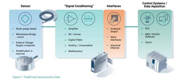
The traditional setup of a strain gauge measurement chain is shown in the diagram below. The sensor works pas- sively and requires a precise external voltage supply. The output signal is ampli-fied and digitised. Both those functions take place in the bridge amplifier. The sensor and the am-plifier are connected using a high-quality measurement cable. Nowadays, measurement amplifi-ers usually feature signal processing capabilities such as filters, peak detection, averaging and many more. The measured signals are output in either analogue or digital format via the amplifi-er’s communications interface and transmitted to the higher-level controller.
The new generation of digital sensors combines the sensing element, the amplifier, analogue-digital conver- sion, signal processing, and the communication interface into a single unit.

 In addition to signal processing (scaling, linearisation, filtering), modern microprocessors also make it possible to perform domain-specific algorithms and sensor health monitoring functions in the sensor. These can be check- weighers and filler algorithms (for weighing applications), or a power calculation (in the case of torque measure- ment). Statistical process parameters such as min/max values, peak-to-peak values as well as sensor-health related parameters can also be calculated based on the sensor-specific mechanical and thermal limits stored within the sensor and the actual measurement values. Paired with an IO-Link interface, the measured values, calcu-lation results and additional information can be easily and efficiently transferred to the PLC sys-tem in a standardised way.
IO-Link solution overview
IO-Link is a highly suited solution to meet the needs of the evolving automation environment. It is an open standard (IEC 61131-9) and enables a point-to-point connection between IO-Link devices and IO-Link masters. The IO-Link standard applies to the communication protocol and the electri-cal wiring and the device data structure.
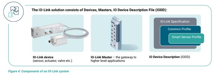
The IO-Link system solution consists of IO-Link devices (sensors, actuators, or other field devices), the IO-Link masters, and the IODD (IO Device Description) files. The IODD contains a description of all sensor and domain- specific functionalities using a standardised data format and structure. There are different sensor profiles for specific sensor categories such as simple switches or digital measuring sensors.
HBK employs the Smart Sensor Profile, enabling the integration of domain-specific algorithms and sensor-spe- cific details through a standardised operating and para- metrisation process that remains consistent across all IO-Link sensors. IO-Link masters act as gateways connecting the individual IO-Link devices via point-to-point com-munication and provide the interface to the higher-level control architec- ture (PLCs) and IT-level applications. IO-Link masters are available for all common fieldbuses and Industrial Ethernet pro-tocols. This makes the IO-Link system solution independent in terms of fieldbus use and provides great flexibility for companies in configuring their system architecture at the field level. This flexi-bility enables easy adaptation to different PLC architectures.
IO-Link offers the potential of unifying the vast signal type, cable, and connector landscape in the field-level via a standardisation of the aforementioned elements. IO-Link data is transmitted through a three-wire, unshielded cable (max. 20 m between device and master) communicating on a 24 V level. Compared to the analogue output of passive strain gauge sensors, this signal type is signifi- cantly more robust, providing high resistance against EMC/EMV influences. Electrical installation becomes easier as there is no need for the sensor and instrument to share the same level of electrical potential. This is required in traditional measure- ment chains to pre-vent current flow over the shielding of the measurement cables.
HBK IO-Link sensor benefits
HBK smart sensors with IO-Link interface offer a wide array of innovative features and benefits for system architects and those involved in designing new or retrofit- ting machines. Next, we will explain the main technical features and technological foundations.
The exact data structure of the aforementioned data types is described in the Smart Sensor Pro-file and IODD (IO Device Description) file. Each HBK IO-Link sensor has its own IODD file. HBK’s IO-Link sensors fully comply with the standard to ensure seamless interoperability. Each IO-Link device, whether a sensor or actuator, is assigned a unique device ID. This identifier ensures accurate sensor identification to correspond with the correct IODD file and provides an additional specific advantage. The sensor’s parameter set can be stored on three levels – within the sensor itself, on the IO-Link master and within the PLC. This triple-level parameter storage concept enables the ‘hot’ swopping of sensors. Using a specific setting, the IO-Link master reads whether the newly connected sensor has the same Device ID as the previous one and automatically writes the stored parameter data into the new sensor if the Device ID matches.
Solution efficiency
Sensors with IO-Link communicate data between them- selves and an IO-Link master. The meas-urement values and other process-relevant values such as the status of the limit switches are transmitted cyclically. The cyclic data is called ‘Process Data’. Additionally, ‘On-Demand Data’ is transferred acyclic. The on-demand data consists of the entire sensor parameter data, which can be accessed by the IO-Link Master, or the higher-level PLC as needed. A further feature of the IO-Link communication protocol is the so called ‘Events’. These are standardised alerts that are triggered when sensor-specific limits are overrun.
The general process of IO-Link sensor integration and parametrisation is the same for all IO-Link devices. The IODD file enables the sensor to be interpreted by any IO-Link compliant engineering tool. Integrating HBK’s IO-Link sensors into most common PLC programmes is efficiently achieved through function blocks that translate the sensors’ cyclic and acyclic data into the PLCs required data type format. This eliminates the need for reading object dictionaries and object addressing.
Performance Analysis
By integrating electronics along with sensor-specific characteristics stored within the sensor, sig-nificant accuracy improvements are achieved. Below, we’ll discuss the performance of HBK IO-Link sensors.
Accuracy
Integrated signal processing capabilities and scaling functions like signal linearisation enhances the accuracy of HBK IO-Link sensors.
HBK IO-Link force and torque sensors offer a tabular (21 points) and polynomial linearisation func-tion. This means that tensile and compressional (force) as well as right/left torque stepwise cali-bration data can be entered.
When combined with calibration, two significant advantages can be attained:
- The tensile/compression respectively the left/right sensitivity deviation is compensated to nearly zero.
- Compensation of the linearity error up to the physical limit
Depending on the sensor, a linearisation and factory calibration in both directions is within scope of delivery. HBK offers a traceability concept for IO-Link sensors, including the input of the supporting points in the sensor. If calibration is performed in the HBK calibration lab, the sensor will be ready to measure on arrival.
Signal runtime and cycle time
The overall signal runtime of an IO-Link device and master setup is made up of the signal runtime of the sensor and the resulting cycle time between the IO-Link device (sensor) and the IO-Link master. The signal runtime of the sensor is the sum of the different processing blocks the signal runs through in the sensor, that is, ADC conversion, scaling and processing, etc. The overall signal runtime is typically measured from the physical impact to the signal output – in this case, this is the time when the signal is ready for output at the sensors
IO-Link transceiver. The runtime is also calculated with filters switched off. The filter delay times are added on top if runtimes with active filtering need to be calculated. The resulting device-master cycle time is defined by the IO-Link device cycle time and the IO-Link master cycle time. The device cycle time is the minimal time it takes the device to ‘cyclically’ send the process data to a master. To realise the minimal device cycle time, the connected IO-Link master must feature a lower cycle time than that of the device.
Example calculation for U9C IO-Link:
• Sensor cycle time 0.9 ms, sensor signal runtime
(filters off) 300 μs
• IO-Link Master cycle time 1 ms
• Physical Impact t = 0
• Sensor signal runtime (filters off) t = 300 μs
• Device-master cycle time t =1 ms
Overall signal runtime (device-master, filters off) = 1.3 ms
The total signal runtime, including the device (sensor), master and PLC, must also consider the IO-Link master’s signal processing runtime (the time it takes for the signal to be output ready at the fieldbus interface) and the PLC cycle time. Such a system setup must be evaluated individually depending on the PLC hardware used and overall application configuration.
Sample rate and bandwidth
HBK IO-Link sensors feature state-of-the-art, integrated strain gauge bridge amplifiers, which are designed for high dynamic and static signal processing of the electrical signal output of the sen-sor’s strain-gauge bridge. For example, HBK IO-Link force sensors measure with a 40 kHz sam-pling rate, which enables the detection of high dynamic characteristics of the measured force sig-nal. The 40 kHz sampling rate is also the internal sampling rate, which is used for statistical pro-cess functions such as min and max values, limit switches, peak-peak etc., and the sensor health monitoring system.
IO-Link Performance – Sample Rate, Bandwidth
The overall signal-bandwidth that can be accurately measured and transmitted is defined by the measurement arrangement of the sensor and mounting situation, as well as the sample rate of the integrated amplifier. Real world measurement signals can be described as a superposition of sinusoidal oscillations. As a practical rule to accurately measure a sinusoidal wave, a sampling rate that is ten times higher than the frequency of the input signal is required. In our case the device has a sampling rate of 40 kHz, leading to a bandwidth of 4 kHz. The sensor’s statistical functions, the sensor health monitoring and the limit switches all work correctly to this high frequency as only internal processing is used.
The maximum frequency of a sinusoidal oscillation to be transmitted from device to master de-pends on the device to master cycling time – see example above.
Pre-processing capabilities
Currently, a common approach is to perform process related calculations within the PLC system. However, as systems grow larger and challenges become more complex, this method puts notable pressure on computational resources and network traffic. Moreover, domain-specific algorithms are often not readily available as plug-and-play solutions, necessitating custom development that demands substantial engineering capacity.
With HBK’s IO-Link solution and extensive expertise in domain-specific algorithms, standard cal-culations are performed inside the sensor, providing access to concise results, and eliminating the need to sift through vast amounts of measurement data. For example, instead of dealing with a data stream, users can simply retrieve the peak value. These domain-specific statistical and pro-cess algorithms are designed to provide the necessary results for the underlying automation, test-ing or manufacturing process. The table below lists the domain-specific statistical and process-related algorithms as well as digital IOs imple- mented in HBK’s IO-Link sensor portfolio.
Force:
- Domain-specific features: 40 kHz internal sampling rate for high dynamic sensing and pre-processing, linearisa-tion (table, polynomial)
- Domain-specific algorithms: peak value detection, span detection, limit switches, two filter stages (Bessel,Butterworth). Adaptation of calibration results (byusing the coefficients on the calibration certificate)
- Analogue process control: one digital Out (additional digital Out available when IO-Link data transmission is disabled)
Load:
- Domain-specific features: weighing technology filters (up to five filter stages cascadable: FIR, IIR, Comb and moving average filters)
- Domain-specific algorithms: filler and check weigher algorithms • Factory scaling implemented on delivery, additional Teach-In assistant for mounted cell calibration with proofing weights
- Analogue process control: one digital IO (additional digital IO available when IO-Link data transmission is disabled)
Torque:
- Domain-specific features: auxiliary information (rotational speed, angle, temperature (rotor/stator), linearisation (table, polynomial))
- Domain-specific algorithms: power calculation, peak value detection, span detection, limit switches, two filter stages (Bessel, Butterworth)
- Adaptation of calibration results (by using the coeffcients on the calibration certificate) • Analogue process control: one digital Out (additional digital Out available when IO-Link data transmission is disabled)
Reliability
Common to all HBK IO-Link sensors is a sensor health monitoring feature. The sensors have their sensor-specific mechanical load and thermal limits stored within the unit and these limits are tracked continuously. Storing the individual limits of a measurement range in the unit is advantageous enabling comparisons between physical impacts on the sensor such as load or a temperature – and these pre-set limits. When the limits are exceeded, the sensor generates a warning independently, operating as a second signal path unaffected by user settings. As a result, any overload, or overheating triggers a warning, which is stored within the sensor for later analysis. If an exceedance is detected, the sensor triggers a standardized IO-Link warning event.
IO-Link and HBK – the way forward
Investing in HBK sensors with IO-Link is not only a step towards modernising manufacturing pro-cesses but also a strategic move that promises a low total cost of owner- ship (TCO) and high re-turn on investment (ROI). This technology enables instant cost savings across various levels, in-cluding component, related, and labour costs. By upgrading processes and utilising existing infra-structure and human resources, companies can gain a competitive edge. The broad HBK portfolio of IO-Link capable sensors spans multiple domains, reflecting our com-mitment to this enduring technology. As industries evolve towards smarter manufacturing, our extensive experience in sensor solutions drives product innovation through virtual, physical, and in-process testing across the product lifecycle. Moreover, HBK serves as a trusted supplier, offering technical consulting, learning opportunities through the HBK academy, and a global webshop. Our service and support network, powered by skilled engineers and technicians, ensures exceptional service at every phase of your testing and measurement projects, making an investment in HBK IO-Link sensors a secure, future-proof choice.