Measuring press forces: accurate, cost effective and reliable
Press force is a crucial parameter for monitoring, quality assurance and force control in presses. As requirements in these areas continue to rise, press force measurement has become increasingly important and is now a standard practice.
How to measure press force
In general, there are two primary methods for measuring forces in pressing processes:
- Direct force measurement
This method involves installing a force transducer i directly in the path of the force withing the pressing machine. Typical sensors used include the C6b sensors and, in some cases, the high precision force transducers U10M or U10F. This approach allows for the most accurate force measurements, as these sensors come pre-calibrated, enabling immediate measurements without the need for on-site calibration.
Press forces can be very high, reaching up to the Meganewton range. While HBK offers force sensors capable of handling these high forces, it’s important to note that these models can be quite heavy, sometimes exceeding 100 kg, and their installation requires significant effort.


Typical sensors used include the C6b sensors and, in some cases, the high precision force transducers U10M or U10F
- Indirect force measurement
Indirect fore measurements are performed by using strain gauges or so-called strain links, or extensometers, such as the SLH700 series from HBK.

The press force is transferred through machine frame, causing strain on the surface of the force leading [SC1] machine parts. In many cases, this strain is linearly related to the press force. Strain links are installed at suitable locations on the press, converting the strain into a measurable voltage signal. This principle has been known for decades and used in thousands of applications.
If the goal is to measure the force in Newtons or another unit, calibration is required after mounting the strain link. This involves substituting the pressing tool and/or workpiece with a reference sensor. Force is then applied to the setup, and the output signals from both the reference force transducer and the strain link are measured in parallel. This process must be performed for at least one force, though it is common practice to use several load steps and repeat the calibration. By considering the force measurement and the strain link output, the sensitivity of the strain link can be calculated, enabling force measurement in Newtons using an extensometer.
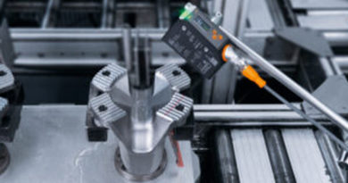
Mounting strain gauges is easy, as the devices are installed with just two M6 screws on the press. It is important to remove any paint and ensure the surface is grease-free. However, since the required force for an SLH strain link is low (just 600 N for a strain of 500 µm/m), the preparation requirements for the measurement point are minimal.
The optimal mounting locations can vary depending on the specific case. See examples in the pictures below.
While strain links may not offer the same precision as force transducers, they come with several advantages:
- Since there is no sensor in the force path, the stiffness and dynamic characteristics of the press remain unchanged
- The cost of force sensors in the Meganewton range significantly higher compare to strain links, making press monitoring with strain links much more economical
- Installing strain links is much simple
Passive or active strain links?
Strain links are available as passive strain gauge-based sensors, which require an amplifier module to amplify the small output signal and provide a usable signal to the control system.
There are also extensometers with built in amplifiers, eliminating the need for an external amplifier module. Which version is suitable in which situation?
When using a single strain link, models with built-in amplifiers are generally more cost effective and provide a more reliable output signal (current or voltage output instead of mV/V signal).
In many cases, strain links are connected both electrically and mechanically in a parallel mounting configuration. This setup is often used to minimise the influence of bending on the measurement result.
In case of pure tensile or compressive strain, both sensors in the example above measure the same strain in the same direction. If bending occurs, one element measures positive strain while the other element measures negative strain. This results in a zero output, achieving bending moment compensation.
It is also possible to use four sensors from the SLH series and connect them in parallel. However, a parallel setup is much easier with non-amplified extensometers and an external amplifier. The passive SLH are designed for this measurement situation: their high input resistance of 1000 Ohms allows for the connection of four or more sensors in parallel without issues related to low sensor impedance with standard market instruments. Additionally, the sensors are adjusted for the relationship between output resistance and rated output, which is important for parallel setups.
Teach-in procedure with amplifier extensometers of the SLH series
Many available strain transducers with an integrated amplifier module only have a fixed amplification. For example, 500 µm/m corresponds to an output signal of 10 V. The fundamental drawback of this method is that the maximum output signal depends upon the given amplification, which cannot be changed. If, a strain of 200 µm/m is used as the input signal, the resulting output voltage is 4 V. This can lead to unsatisfactory results, if the next element in the measurement chain is a module that has a low resolution or increased noise.
SLH700VA strain links with integrated amplifier electronics overcome this problem by providing the maximum possible output signal at all times, regardless of the intended purpose.
The teach-in procedure is simple:
- Install the sensor as usual and reduce the load on the machine (press, roll stand, silo) to zero. Send a longer pulse to the teach-in input to allow the electronics to memorise the zero point
- Apply the calibration load and send a short pulse to the teach-in input. This adjusts the electronics between the zero point and the calibration load
- This process ensures that the input range of the next level is fully utilised at all times
- The teach-in procedure can be performed at 25%, 50%, or 100% of the full scale
Additional advantages of this procedure:
- There is always a 10% buffer in the upper and lower parts of the measuring range. Higher strain signals, such as those occurring during a failure, failure) are still amplified and transmitted
- The characteristic curve can be negative, allowing both elongation and shortening to be converted into a positive signal
- The built-in measuring amplifier provides low noise and a bandwidth of 2 kHz
- It is essential to permanently store the span, which is the difference between the minimum and maximum values. Therefore, resetting to zero after a power failure is imperative
Why choose SLH extensometers?
SLH sensors offer a cost effective and reliable alternative to load cells for press force measurement with load cells. Here are some key benefits:
- With an IP68 protection rating, the sensors and cables are resistant to most oils and water, and can be used on drag chains All materials are rust free, ensuring reliable measurements in harsh industrial environments
- The low force shunt means that the sensor’s influence on the press is negligible.
- Mounting requires just two screws and no special tools
- Users can choose between amplified and passive versions depending on the measurement situation. Both models have the same outer dimensions, allowing for easy exchange
- The amplified version supports partial teach-in functionality, making it suitable for situations where applying the full range force is not possible, such as in dynamic presses